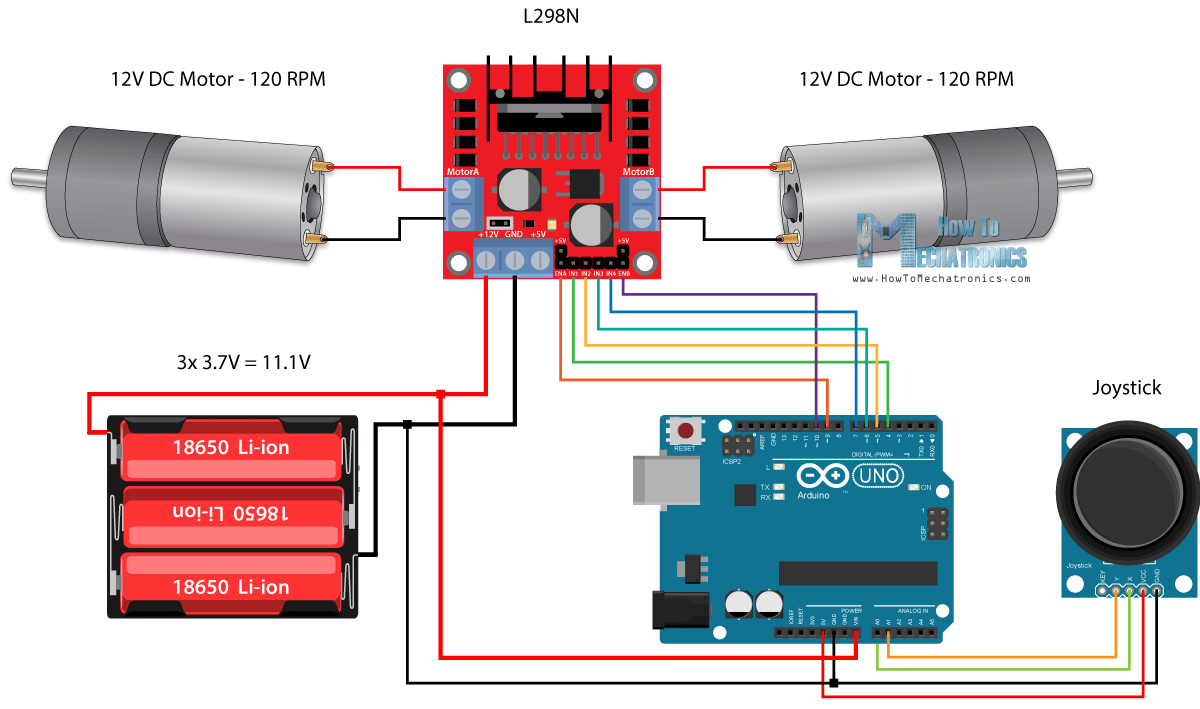

- #Two dc motors arduino code how to#
- #Two dc motors arduino code driver#
- #Two dc motors arduino code code#
whether its moving in clockwise direction or anticlockwise. Moreover, I have also used LCD which will give us the status of our DC Motor i.e. In this tutorial, I will do the DC Motor Direction Control using Arduino and L298 motor controller. You can use it in automation projects, for controlling static as well as mobile robots, in transport system, in pumps,fans,bowers and for industrial use as well. You should also have a look at Difference between DC & AC Motors to get a better idea about these motors.ĭC motor has a lot of applications. If you change the polarity then motor will rotate in opposite direction. If we connect these terminals with the voltage supply the motor will rotate. So, a direct current motor is commonly used motor having two input terminals, one is positive and the other one is negative. The word DC is basically an abbreviation of Direct current.
#Two dc motors arduino code how to#
Today, I am going to share my knowledge with all of you about how to make a simple program for DC Motor Direction Control using Arduino. To take this one step further, connect your device to Wia and add Commands and Flows.Hello friends! I hope you all will be absolutely fine and having fun. If you want to change the direction, simply reverse HIGH and LOW in the loop function. Once the sketch is uploaded successfully, the motor will turn in one direction.
#Two dc motors arduino code code#

Once that's all connected, it should look a little something like this: Simply connect the negative lead to GND on the breadboard, and the positive lead to the Vs pin of the L293D. If your motor requires more voltage than your Arduino can provide, you can hook up an external battery or battery pack.
#Two dc motors arduino code driver#
Note: The Vs pin on the motor driver supplies power to the motor. Finally, connect output 1 and output 2 of the L293D to your motor pins.Connect your Arduino's GND to both GND pins on the same side of the L293D.Connect digital output pins (we're using 6 and 7) to input 1 and input 2 on the L293D.Connect 5V to Enable 1, Vss, and Vs on the L293D.Place the L293D in the center of the breadboard, with half of the pins on either side of the breadboard.Connect the GND and 5V on the Arduino to one side of the breadboard, and extend them to the other side with jumper wires.Start by plugging your Arduino into a power source (such as your computer).

Since we're just driving one motor for this tutorial, we won't be using all of the motor driver's pins. Below, you'll see a pin diagram of the L293D - note the location of each of the pins, relative to the notch at the top. The L293D is a 16-pin Motor Driver IC which can control up to two DC motors simultaneously, in any direction.įirst, let's hook up the components on the breadboard. In this tutorial, we'll be looking at how to power and drive a DC motor with an L293D and an Arduino (we're using the Arduino MKR 1000 here, but you can use any Arduino that provides enough voltage for your motor and has 2 digital output pins).


 0 kommentar(er)
